
9 June 2008
8 June 2008
Major Assignment - Physical Model Complete!
Here are photos of the completed model:
 I cut away at the first floor wall on one side to continue with the cut made by the bearer to show the reo connection.
-------------------------------------------------------
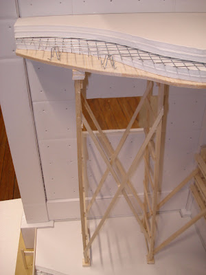
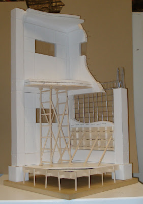 I built scaffolding to hold up the first floor to show illustrate the construction process for in-situ suspended floor slabs. Another way would have been to use a 'bondek' material to support the floor but I feel that Ando would have used removable form work rather than a permanent solution.
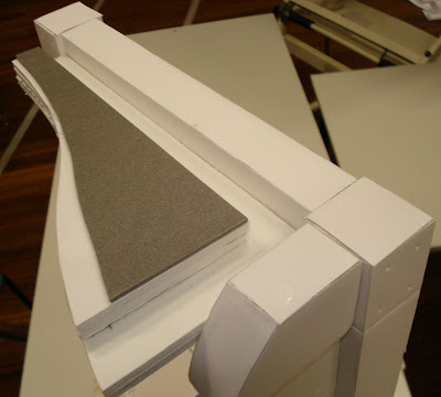 The grey material is supposed to represent asphalt. The box gutter should have a 1:200 slope. The roof should also have a slight slope of 2-3 degrees so that the water doesn't puddle but flows to the gutter.
-------------------------------------------------------
-------------------------------------------------------
 I cut away at the first floor wall on one side to continue with the cut made by the bearer to show the reo connection.
 I built scaffolding to hold up the first floor to show illustrate the construction process for in-situ suspended floor slabs. Another way would have been to use a 'bondek' material to support the floor but I feel that Ando would have used removable form work rather than a permanent solution.
 -------------------------------------------------------
 The grey material is supposed to represent asphalt. The box gutter should have a 1:200 slope. The roof should also have a slight slope of 2-3 degrees so that the water doesn't puddle but flows to the gutter.
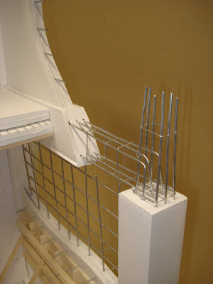
I had a bit of fun making bar stools for the reo to sit on. These can be made of plastic as well as steel. I was thinking about it after, and I'm not sure if there would be two layers of reo in a 200mm slab like this. I think it would be up to the structural engineer to choose either one layer of heavier reo or two layers of lighter reo. It probably also comes down to cost also.
-------------------------------------------------------

How the bearer connects to the column. Ligatures would be more closer together at connections like these.
7 June 2008
Major Assignment - Physical Model Update 2
Update from work on model today, worked for 8 hours and still haven't finished... Will get the rest done tomorrow.


--------------------------------------------------------


--------------------------------------------------------

--------------------------------------------------------
Ground Slab: Here I have shown the ground slab with all the components used. The form work, gravel, membrane, mesh and concrete.

--------------------------------------------------------
Formwork: I needed to shorten the bracing on the outside because it would hand out further than the base. I have also left out the piece of the form ties that sits on the outside of the walers. I think it would be too much to show this in the model. I will show a detail of how it will properly look in the poster.

--------------------------------------------------------
Detail of the re-enforcement: It took me quite a while to get all the wire to sit together straight and even. I had to tie the bent horizontal reo to the vertical reo because it wasn't going to sit on its own and my glue didn't hold.

6 June 2008
Major Assignment - Physical Model Update
Here is where I am so far:


Still going... I need to build up the formwork wall and the first floor slab and roof.


Still going... I need to build up the formwork wall and the first floor slab and roof.
2 June 2008
Major Assignment - Physical Model Update
Yesterday I bought what materials I thought I needed to start the model today. So far I haven't made much progress in a 3D sense, but I have cut up a lot of foam core to make the columns and bearers. I have decided to cut off the edges at 45 degrees so the there is a seamless connection between the faces of foam core. Haven' t got any photos up because I left my camera at home but hope to put some on soon.
I still haven't got any wire for re-enforcing but will have to get some asap. I'm not really sure if I will be able to get this model as well as the poster done by Friday. I might email my lecturer about it tomorrow.
Form-work:
I still haven't got any wire for re-enforcing but will have to get some asap. I'm not really sure if I will be able to get this model as well as the poster done by Friday. I might email my lecturer about it tomorrow.
Form-work:
Form-work is just as important If not more important than the concrete in in-situ construction. I have looked at a few books from the library but the most useful and most detailed has been the book I got info on the re-enforcement I put up earlier. The book is: E Allen, J Iano, ‘Fundamentals of Building Construction, Materials and Methods’, Fourth Edition, John Wiley and Sons Inc., New Jersey 2004.
Some form-work drawings I have traced:

----------------------------------------------------
Some form-work drawings I have traced:

----------------------------------------------------

31 May 2008
Major Assignment - Update
Well, the idea of drawing up a CAD model has been officially thrown out the window. I imagine a physical model will be a lot more work but surely it wont be as frustrating as it has been for me working on CAD.
I have been working out dimensions and stuff for a 1:10 model and it works out that at this scale the model will br 340mm length x 340mm depth x 7000mm height. This seems to me to be alright, the risk is that not enough detail will be shown but I will try my best. On the Assignment instruction it does say to make a 5m x 5m section but I have chosen to do a 3.4m x 3.4m section because that it the span between two columns. Making the section model from a 6.8m x 6.8m section will not actually bring more information or detail to the model because it would just be repetition. The height from floor to ceiling I made at 3.6m and width I wanted to be as close to this as possible so that the grid was cubic.
Below is a photocopy of my workings sheet:
 On the above image there is also a rough diagram of how I think the footings will look (bottom left) and how I want the model to show peeling away of layers on each floor.
29 May 2008
Major Assignment - In-situ concrete CAD drawing
I have been trying for a few days to draw this really good detail but I have been having a really hard time. Here is the grid that I imagine and I'm trying to draw the ligatures but I have not had much luck with the cad tools thus far.

Detail that I want to draw:
 Image from: ‘E Allen, J Iano, ‘Fundamentals of Building
Construction, Materials and Methods’, Fourth Edition, John Wiley
and Sons Inc., New Jersey 2004
My drawing so far:

I haven't really shown all my tries at different ways of making a wrapping ligature here. Its just getting really difficult and getting frustrated with it. I have asked a few of my friends for help as they are a bit better at CAD than me but I they cant work it out either. I have tried micro station and 3D Autocad tools. The whole point of in-situ is the re-enforcing and the form work so its no use leaving it out of my drawing.
If I don't work things out by tomorrow, I might have to resort to making a physical model. I'm just not familiar enough with CAD. I will make up my mind tomorrow.
27 May 2008
Major Assignment - Change of plans
Ok, so I have decided that the design that I want will not work with pre cast concrete and I have tried and tried to make it work.
I am now going to use in-situ concrete to build. Here are some notes I have made on the topic:

Tonight I hope to start on a CAD drawing for the re-enforcing in the columns and the connection to the beams. We will see how this goes...
I am now going to use in-situ concrete to build. Here are some notes I have made on the topic:

Tonight I hope to start on a CAD drawing for the re-enforcing in the columns and the connection to the beams. We will see how this goes...
25 May 2008
Major Assignment - CAD Drawing Update 1
Here is what I have been working on today. I made a column with an edge for the beams to sit on. I'm not really happy with the way that this will come together as it isn' t very clean. Ando's insitu designs would not have had such a messy edge piece.


24 May 2008
Major Assignment - CAD Drawing
Here is what I have managed to draw so far in CAD.
I'm still haven't put a corbel in and I'm not sure how even the grid will look once its in.

I'm still haven't put a corbel in and I'm not sure how even the grid will look once its in.
23 May 2008
Major Assignment - Warehouse Plan and Elevation
Here is the CAD drawing I drew up today showing how I want the warehouse to look.


I'm still not sure about how the windows are going to look in the office block. Tadao Ando would have done something similar to this:
 Tadao Ando, 'Matsumoto House', Wakayama,1979-80
-------------------------------------------------
 Tadao Ando, 'Onishi House', Osaka, 1979
-------------------------------------------------


(click on the image to see in close up)

I'm still not sure about how the windows are going to look in the office block. Tadao Ando would have done something similar to this:
 Tadao Ando, 'Matsumoto House', Wakayama,1979-80
-------------------------------------------------
 Tadao Ando, 'Onishi House', Osaka, 1979
-------------------------------------------------
In an Australian context, I don't think covering the whole wall with glass is a viable solution. Thats why in the elevation I have divided up the wall panel and put a smaller window at eye level instead. Still not sure if I will change the windows on ground floor to be different from first floor.
Plan:
Plan:

So the car park will be wrapped by the wall extending from the office block. The dimensions of the warehouse have been skewed slightly from the original given so that they will play in nicely with the grid pattern.
21 May 2008
Major Assignment - Hollow Core Research Update 4
Just putting up some of the details I found in the manuals from the 'National Precast Association Australia' www.npcaa.com.au
'Hollowcore Walling- Technical Manual', National Precast Association Australia, 1992
'Hollowcore Flooring- Technical Manual', National Precast Association Australia, 2003
Plank to plank connection:
 'Hollowcore Flooring- Technical Manual', National Precast Association Australia, 2003, p.16.
'Hollowcore Walling- Technical Manual', National Precast Association Australia, 1992
'Hollowcore Flooring- Technical Manual', National Precast Association Australia, 2003
Plank to plank connection:
 'Hollowcore Flooring- Technical Manual', National Precast Association Australia, 2003, p.16.
----------------------------------------------------
Bearing support details:
 'Hollowcore Flooring- Technical Manual', National Precast Association Australia, 2003, p.17.
----------------------------------------------------
Plank to beam details:

----------------------------------------------------
Bearing support details:
 'Hollowcore Flooring- Technical Manual', National Precast Association Australia, 2003, p.17.
----------------------------------------------------
Insitu connection detail:

----------------------------------------------------


'Hollowcore Walling- Technical Manual', National Precast Association Australia, 1992, p.14-15.
----------------------------------------------------
Wall panel fixing details:


'Hollowcore Walling- Technical Manual', National Precast Association Australia, 1992, p.14-15.
----------------------------------------------------
Typical panel details at roof:

20 May 2008
Major Assignment - Hollow Core Research Update 3
I have been reading a few books on hollow core and here is the notes I have got so far to help me with my assignment.
Hollow core:
- Pre cast, pre stressed, excellent fire resistance
- Allows for fast construction as made off site
- Planks are 1200mm wide, thickness between 150mm-400mm
- Wall panels are standard widths of 1200mm-2400mm
- Casting bed is between 120m-170m in length, planks saw cut to size
- The voids allow sound insulation, reduce dead weight, conceal wiring and ducts, eg. lighting circuits. Slabs with heated are through cores can be used as a thermal mass in passive solar application.
- Topping on floor planks is a cement based skim coat to top surface of slabs. This allows direct installation of floor coverings as well as allowing the floor to act as one composite element.
- Structural topping a minimum of 60 mm thick for up to 200mm deep planks, 80mm thick for 300mm deep planks. Topping provides a level working surface.
- Non structural topping usually self leveling mortar at 10-15 mm average thickness
- Camber- topping thickness to follow camber of the planks or not, varies with each situation.
- Construction joints- saw cut made within 18 hrs of casting topping
Book list
Verge, G.C, 'Hollow core floor technical manual', 2nd ed, National precast Concrete Association of Australia, North Sydney, 199-
'Tilt-up construction notes / Cement and Concrete Association of Australia', Cement and Concrete Association of Australia, North Sydney, N.S.W., 1997
'Guide to concrete construction / a joint publication of Cement and Concrete Association of Australia and Standards Australia', 2nd ed., Cement and Concrete Association of Australia ; Homebush, Standards Australia, 2002
Helpful websites
- National Precast Association Australia, www.npcaa.com.au
Two manuals I was able to download have been even more helpful than the above books which I found in the library. They are:
'Hollowcore Walling- Technical Manual', National Precast Association Australia, 1992
'Hollowcore Flooring- Technical Manual', National Precast Association Australia, 2003
- Concrete Institute of Australia, www.coninst.com.au/
18 May 2008
Major Assignment - Hollow Core Research Update 2
Ok, well here is where I am with the hollow core research so far:
The ground floor will have a poured slab and strip footing system so the research into hollow core planks will only apply to the first floor and roof, columns and bearers. The planks which I want to span the first floor for about 8m (not 15m), according to the span chart provided by www.hollowcore.com.au will need to use 205mm thick hollow core. (link to detailing manual)
- Load span chart:
 Image from 'Detailing Manual', p. 7., www.hollowcore.com.au
-----------------------------------------------------------------
I've also found some great details which may assist with understanding how this will all get put together:
- Detail of beam, column, hollow core connection:
The ground floor will have a poured slab and strip footing system so the research into hollow core planks will only apply to the first floor and roof, columns and bearers. The planks which I want to span the first floor for about 8m (not 15m), according to the span chart provided by www.hollowcore.com.au will need to use 205mm thick hollow core. (link to detailing manual)
- Load span chart:

-----------------------------------------------------------------
- Detail of 205 hollow core plank: Image from 'Detailing Manual', p. 7., www.hollowcore.com.au
-----------------------------------------------------------------
- Detail of beam, column, hollow core connection:

-----------------------------------------------------------------
- Detail of cobel wall to hollow core plank flooring:
-----------------------------------------------------------------
 Image from 'Detailing Manual', p. 36., www.hollowcore.com.au
-----------------------------------------------------------------
 Image from 'Detailing Manual', p. 36., www.hollowcore.com.au
-----------------------------------------------------------------

Image from 'Detailing Manual', p. 40., www.hollowcore.com.au
- Detail of wall to hollow core connection:
 Image from 'Detailing Manual', p. 36., www.hollowcore.com.au
-----------------------------------------------------------------
- Another detail of wall to hollow core connection:
 Image from 'Detailing Manual', p. 36., www.hollowcore.com.au
-----------------------------------------------------------------
- Detail of column base connection:

Image from 'Detailing Manual', p. 40., www.hollowcore.com.au
17 May 2008
Major Assignment- Hollow Core Research Update 1
I looked a little into hollow core products at http://www.hollowcore.com.au/and would like to use hollow core slabs for the floors in the office block on the first floor. I would like to use the product for the walls as well.
For the first floor of the office, I will need to use hollow core that spans over 15m. Below is a drawing of the 400 thick slab that will be used.

For the first floor of the office, I will need to use hollow core that spans over 15m. Below is a drawing of the 400 thick slab that will be used.

15 May 2008
Major Assignment- Hollow Core Research
Following the guest lecture on 'Hollow Core' concrete, 15th May, week 10, and the following tutorial, Chris and I have decided to use a hollow core system instead of in-situ concrete for the warehouse and office block.
In the tutorial Stuart showed us a possibility of how the office would look in section, using a corbel. I would like to use a concrete roof system, which I will have to research.

-------------------------------------------------------------

In the tutorial Stuart showed us a possibility of how the office would look in section, using a corbel. I would like to use a concrete roof system, which I will have to research.

-------------------------------------------------------------
For the warehouse we need to span 50m with minimal columns to break up the space. Thus it has been decided that we will use a steel portal frame roof attached with bolts to the hollow core wall panels.

-------------------------------------------------------------
It has been decided that Chris will do a warehouse section and I will do an office section. I'm kind of interested to see how I can use the hollow core members to make a grid.

12 May 2008
Major Assignment - Warehouse Design Update
After meeting up with my partner Chris Tang we got a few sketches together about how we want the office and warehouse to look. We have settled on a gird kind of design with will be carried through on the warhouse with columns with engaged wall panels. Below are some pictures which we have used for inspiration:
 Tadao Ando, Art Gallery Complex, Tokyo design, 1977

Tadao Ando, Onishi house, Osaka, 1979
-----------------------------------------------------------
 Tadao Ando, Matsumoto House, Wakayama, 1979-80
-----------------------------------------------------------

Tadao Ando, Fuku House, Wakayama, 1979-80
-----------------------------------------------------------
Plan showing a wall extending out from office block to wrap around car park. Also shows a curved wall in the office block with a stairway following and piercing through this wall to the first floor. These kind of details are typical of Tadao Ando. (see images above)

--------------------------------------------------------
Perspective showing how the office block will be a grid
 --------------------------------------------------------
Elevation of the office block
 --------------------------------------------------------
How the warehouse might be put together. Obviously the columns will be repeated either site. I imagine the columns will be engaged with the wall.

This Thursday Chris and I plan to talk to our tutor Stuart about exactly how we can connect the roof to the warehouse, weather we have to use all concrete or perhaps a steel portal frame roof? Also I need some help understanding how the office grid will work in pre cast concrete, or should we design in situ concrete as Ando would have done. I'm pretty sure that pre cast panels could be made to have the form work tie dots that Ando uses as architectural detail.
 Tadao Ando, Art Gallery Complex, Tokyo design, 1977
-----------------------------------------------------------

Tadao Ando, Onishi house, Osaka, 1979
-----------------------------------------------------------
 Tadao Ando, Matsumoto House, Wakayama, 1979-80
-----------------------------------------------------------

Tadao Ando, Fuku House, Wakayama, 1979-80
-----------------------------------------------------------
Plan showing a wall extending out from office block to wrap around car park. Also shows a curved wall in the office block with a stairway following and piercing through this wall to the first floor. These kind of details are typical of Tadao Ando. (see images above)

--------------------------------------------------------
Perspective showing how the office block will be a grid
 --------------------------------------------------------
Elevation of the office block
 --------------------------------------------------------
How the warehouse might be put together. Obviously the columns will be repeated either site. I imagine the columns will be engaged with the wall.

This Thursday Chris and I plan to talk to our tutor Stuart about exactly how we can connect the roof to the warehouse, weather we have to use all concrete or perhaps a steel portal frame roof? Also I need some help understanding how the office grid will work in pre cast concrete, or should we design in situ concrete as Ando would have done. I'm pretty sure that pre cast panels could be made to have the form work tie dots that Ando uses as architectural detail.
Subscribe to:
Posts (Atom)