
9 June 2008
8 June 2008
Major Assignment - Physical Model Complete!
Here are photos of the completed model:
 I cut away at the first floor wall on one side to continue with the cut made by the bearer to show the reo connection.
-------------------------------------------------------
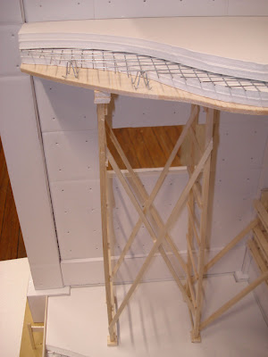
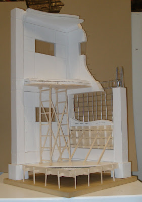 I built scaffolding to hold up the first floor to show illustrate the construction process for in-situ suspended floor slabs. Another way would have been to use a 'bondek' material to support the floor but I feel that Ando would have used removable form work rather than a permanent solution.
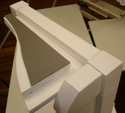 The grey material is supposed to represent asphalt. The box gutter should have a 1:200 slope. The roof should also have a slight slope of 2-3 degrees so that the water doesn't puddle but flows to the gutter.
-------------------------------------------------------
-------------------------------------------------------
 I cut away at the first floor wall on one side to continue with the cut made by the bearer to show the reo connection.
 I built scaffolding to hold up the first floor to show illustrate the construction process for in-situ suspended floor slabs. Another way would have been to use a 'bondek' material to support the floor but I feel that Ando would have used removable form work rather than a permanent solution.
 -------------------------------------------------------
 The grey material is supposed to represent asphalt. The box gutter should have a 1:200 slope. The roof should also have a slight slope of 2-3 degrees so that the water doesn't puddle but flows to the gutter.
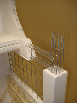
I had a bit of fun making bar stools for the reo to sit on. These can be made of plastic as well as steel. I was thinking about it after, and I'm not sure if there would be two layers of reo in a 200mm slab like this. I think it would be up to the structural engineer to choose either one layer of heavier reo or two layers of lighter reo. It probably also comes down to cost also.
-------------------------------------------------------

How the bearer connects to the column. Ligatures would be more closer together at connections like these.
7 June 2008
Major Assignment - Physical Model Update 2
Update from work on model today, worked for 8 hours and still haven't finished... Will get the rest done tomorrow.


--------------------------------------------------------


--------------------------------------------------------

--------------------------------------------------------
Ground Slab: Here I have shown the ground slab with all the components used. The form work, gravel, membrane, mesh and concrete.

--------------------------------------------------------
Formwork: I needed to shorten the bracing on the outside because it would hand out further than the base. I have also left out the piece of the form ties that sits on the outside of the walers. I think it would be too much to show this in the model. I will show a detail of how it will properly look in the poster.

--------------------------------------------------------
Detail of the re-enforcement: It took me quite a while to get all the wire to sit together straight and even. I had to tie the bent horizontal reo to the vertical reo because it wasn't going to sit on its own and my glue didn't hold.

6 June 2008
Major Assignment - Physical Model Update
Here is where I am so far:


Still going... I need to build up the formwork wall and the first floor slab and roof.


Still going... I need to build up the formwork wall and the first floor slab and roof.
2 June 2008
Major Assignment - Physical Model Update
Yesterday I bought what materials I thought I needed to start the model today. So far I haven't made much progress in a 3D sense, but I have cut up a lot of foam core to make the columns and bearers. I have decided to cut off the edges at 45 degrees so the there is a seamless connection between the faces of foam core. Haven' t got any photos up because I left my camera at home but hope to put some on soon.
I still haven't got any wire for re-enforcing but will have to get some asap. I'm not really sure if I will be able to get this model as well as the poster done by Friday. I might email my lecturer about it tomorrow.
Form-work:
I still haven't got any wire for re-enforcing but will have to get some asap. I'm not really sure if I will be able to get this model as well as the poster done by Friday. I might email my lecturer about it tomorrow.
Form-work:
Form-work is just as important If not more important than the concrete in in-situ construction. I have looked at a few books from the library but the most useful and most detailed has been the book I got info on the re-enforcement I put up earlier. The book is: E Allen, J Iano, ‘Fundamentals of Building Construction, Materials and Methods’, Fourth Edition, John Wiley and Sons Inc., New Jersey 2004.
Some form-work drawings I have traced:

----------------------------------------------------
Some form-work drawings I have traced:

----------------------------------------------------

31 May 2008
Major Assignment - Update
Well, the idea of drawing up a CAD model has been officially thrown out the window. I imagine a physical model will be a lot more work but surely it wont be as frustrating as it has been for me working on CAD.
I have been working out dimensions and stuff for a 1:10 model and it works out that at this scale the model will br 340mm length x 340mm depth x 7000mm height. This seems to me to be alright, the risk is that not enough detail will be shown but I will try my best. On the Assignment instruction it does say to make a 5m x 5m section but I have chosen to do a 3.4m x 3.4m section because that it the span between two columns. Making the section model from a 6.8m x 6.8m section will not actually bring more information or detail to the model because it would just be repetition. The height from floor to ceiling I made at 3.6m and width I wanted to be as close to this as possible so that the grid was cubic.
Below is a photocopy of my workings sheet:
 On the above image there is also a rough diagram of how I think the footings will look (bottom left) and how I want the model to show peeling away of layers on each floor.
29 May 2008
Major Assignment - In-situ concrete CAD drawing
I have been trying for a few days to draw this really good detail but I have been having a really hard time. Here is the grid that I imagine and I'm trying to draw the ligatures but I have not had much luck with the cad tools thus far.

Detail that I want to draw:
 Image from: ‘E Allen, J Iano, ‘Fundamentals of Building
Construction, Materials and Methods’, Fourth Edition, John Wiley
and Sons Inc., New Jersey 2004
My drawing so far:

I haven't really shown all my tries at different ways of making a wrapping ligature here. Its just getting really difficult and getting frustrated with it. I have asked a few of my friends for help as they are a bit better at CAD than me but I they cant work it out either. I have tried micro station and 3D Autocad tools. The whole point of in-situ is the re-enforcing and the form work so its no use leaving it out of my drawing.
If I don't work things out by tomorrow, I might have to resort to making a physical model. I'm just not familiar enough with CAD. I will make up my mind tomorrow.
Subscribe to:
Posts (Atom)